Camera algorithms
MM Solutions EAD is experienced in developing camera solutions, with over 20 years of providing services. The initial steps were camera control and image processing solutions. Upon further development of the company, advanced image processing and calibration algorithms to facilitate image quality tuning were mastered and are to this day offered to clients. Even further Computational photography, multi-frame processing, and computer vision were mastered by our experts. Automotive ultra HDR, surround view, mirror replacement, and other needs of the industry are all included in our services and were adapted to the highest world standards.

CAMERA ALGORITHMS
Menu
CAMERA ALGORITHMS
CAMERA CONTROL
SOLUTIONS
COMPUTATIONAL PHOTOGRAPHY
MACHINE VISION MULTI-FRAME PROCESSING
360 DEGREE PANORAMA
360 STITCHING
BASIC IMAGE PROCESSING
RAW LOW-LIGHT FILTER (MFNR)
ELECTRONIC IMAGE
STABILIZATION (EIS)
SMART ZOOM
CALIBRATION SERVICES
HIGH DYNAMIC RANGE (HDR)
MMS SURROUND VIEW
NIGHT
DISTORTION CORRECTION
AUGMENTED REALITY
CAMERA CONTROL SOLUTIONS
- MMS Auto Exposure Compensation (AEC) algorithm
- MMS AEC is using sophisticated heuristic algorithms in order to calculate the best exposure for a given scene, taking into account not only the brightness of the scene but many additional factors such as minimizing the motion blur in the captured picture, improving details in the shadows, compensating the backlight, etc. AEC for automotive HDR sensors (3 exposures).
- MMS Auto White Balance (AWB) algorithm
- AWB is designed to handle complex corner cases where no white patch is available on the scene or the scene has a predominant color.
- Special attention is paid to the human skin tone and memory colors. When combined with advanced methods to control saturation and color shift, the algorithm produces vivid pictures with excellent color accuracy.
- It has advanced color analysis based on both potentially white colors and memory color detection. Connection to AE for flash AWB.
- MMS Auto Focus (AF) algorithm
- AF provides excellent focusing accuracy. Specially designed algorithms are used to ensure optimal driving methods, minimizing the drive time and increasing speed and accuracy, as well as accommodating a broad range of production tolerances.
- Lens control
- Fast and accurate lens positioning for various types of lens actuators.
BASIC IMAGE PROCESSING
The MMS programmable image pipe provides state-of-the art image quality at a very reasonable computational cost. It was under development for more than 10 years, and most of its building blocks were used in volume production by Tier 1 handset OEMs and DSC makers.
IT CONSISTS OF THE FOLLOWING BLOCKS:
- Data pedestal subtraction and image.
- Defect pixel correction and impulse noise removal.
- Bayer domain scalin.
- Lens and color shading correction.
- Bayer domain noise filter – temporal and spatial adaptive
- Green imbalance correction.
- Edge adaptive CFA
- Overall image pipe – separate edge
enhancement and noise suppression paths. - Demosaicing – adaptive, edge-directed.
- Dynamic IPIPE configuration based on scene characteristics of lens positioning for various types of lens actuators.
- Color conversions – RGB2RGB, RGB2YUV.
- Gamma correction.
- Tone mapping and DRC – GBCE, LBCE.
- RGB domain filtering.
- Color enhancement.
- YUV domain noise filtering.
- Adaptive edge enhancement.
- YUV domain scaling.
- Edge enhancement.
- Denoising – simple edge-directed filters,
frequency domain filters, optimized bilateral filters, IIR approximations of Gausian and bilateral.
CALIBRATION solutions
- Lens shading calibration for normal and fish-eye lenses without expensive all-angle uniform sources.
- Lens distortion correction and factory calibration.
- Mutual camera position calibration for dual and quad camera modules.
- Stereo couple factory and run time calibration as well as rectification.
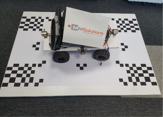
Surround view calibration chart
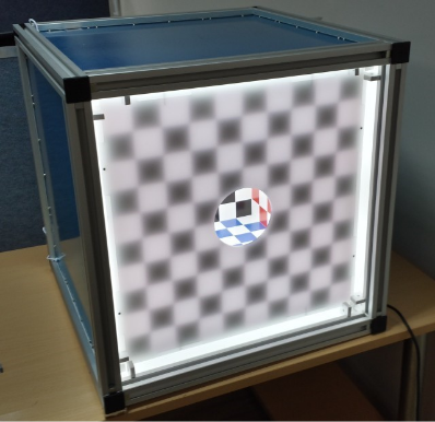
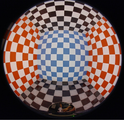
Multi-functional calibration cube
COMPUTATIONAL PHOTOGRAPHY
MACHINE VISION
MULTI-FRAME PROCESSING
- Optical flow.
- Features detection and tracking using edges, but not only corners, on normal HDR, binary and ternary images.
- Frame registration and alignment.
- Camera model estimation and projection from pinhole to Panini and arbitrary distortions.
- Camera pose and orientation estimation RANSAC, ORSA and SCG Use edges too, not only features
- Dewarp, reproject.
- Optimized edge extraction and lines as well as, circle detection.
- Various image segmentations, based on concrete needs.
- Depth map extraction from stereo and moving single cameras.
If you are considering introducing our technology or products, or if you are interested in co-creation with us, please feel free to contact us from here.
HIGH DYNAMIC RANGE (HDR)
- Uses multiple frames from a conventional image sensor captured with different exposure settings.
- The input frame exposure times are determined automatically based on scene analysis.
- Detects moving objects and does not fuse the corresponding areas to avoid ghosting artifacts.
- Embedded local and global brightness and contrast enhancement (tone mapping) to enhance the visual quality of the produced image.
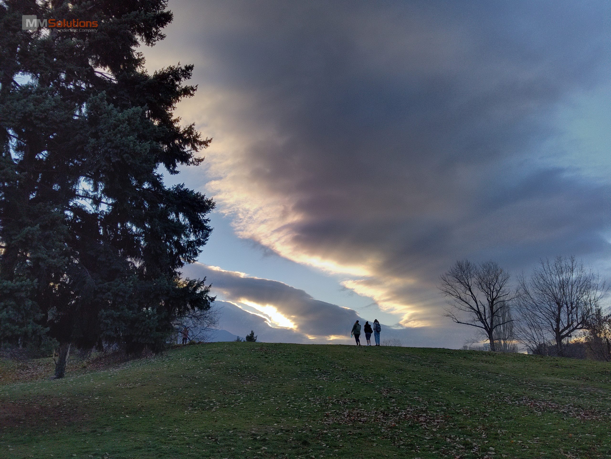
- Low-light HDR combines both technologies—low-light filter (MFNR) and HDR—to output high-quality images with low noise levels and well-preserved highlights. Perfect solution for typical nightscape scenes.
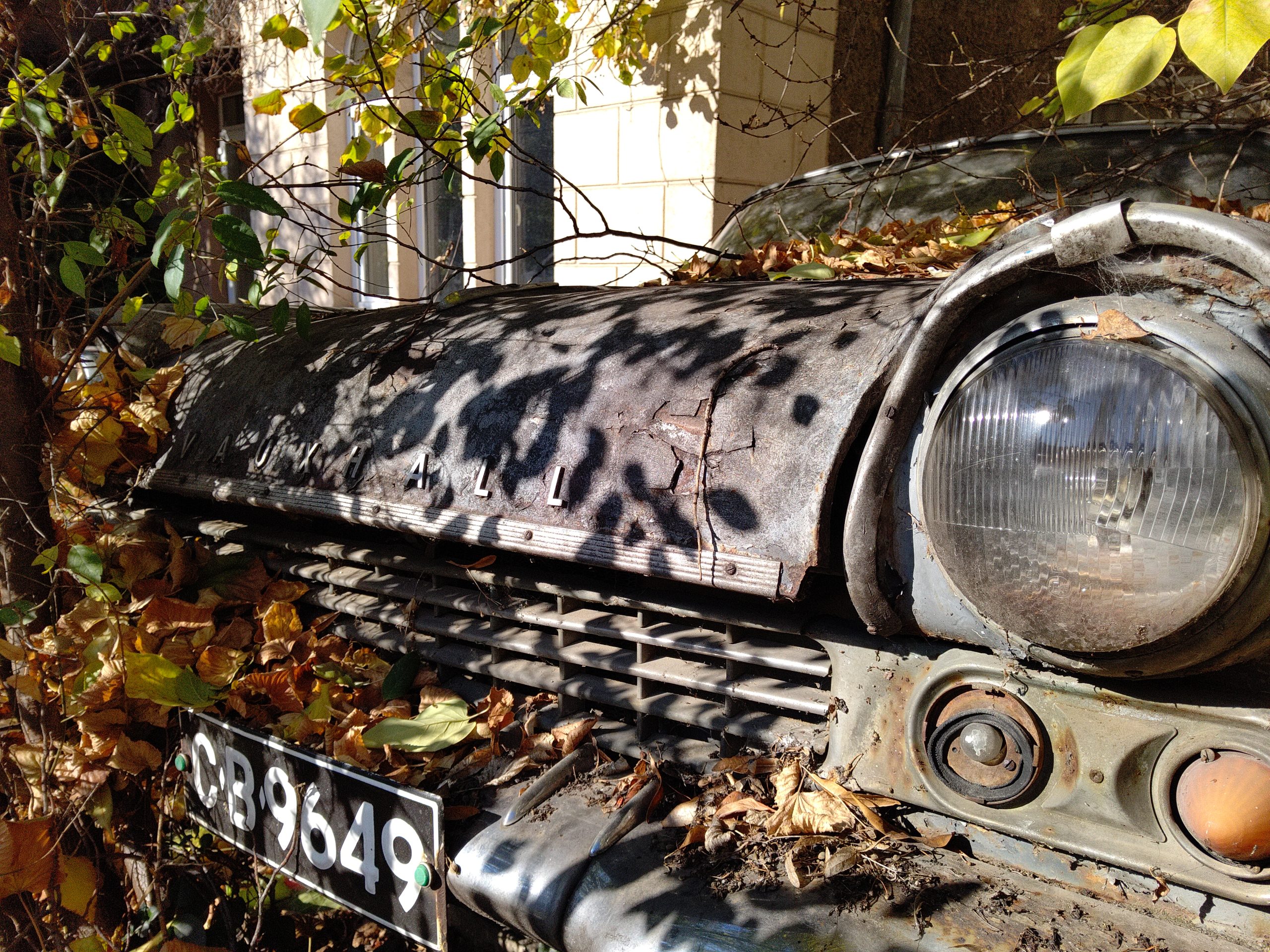
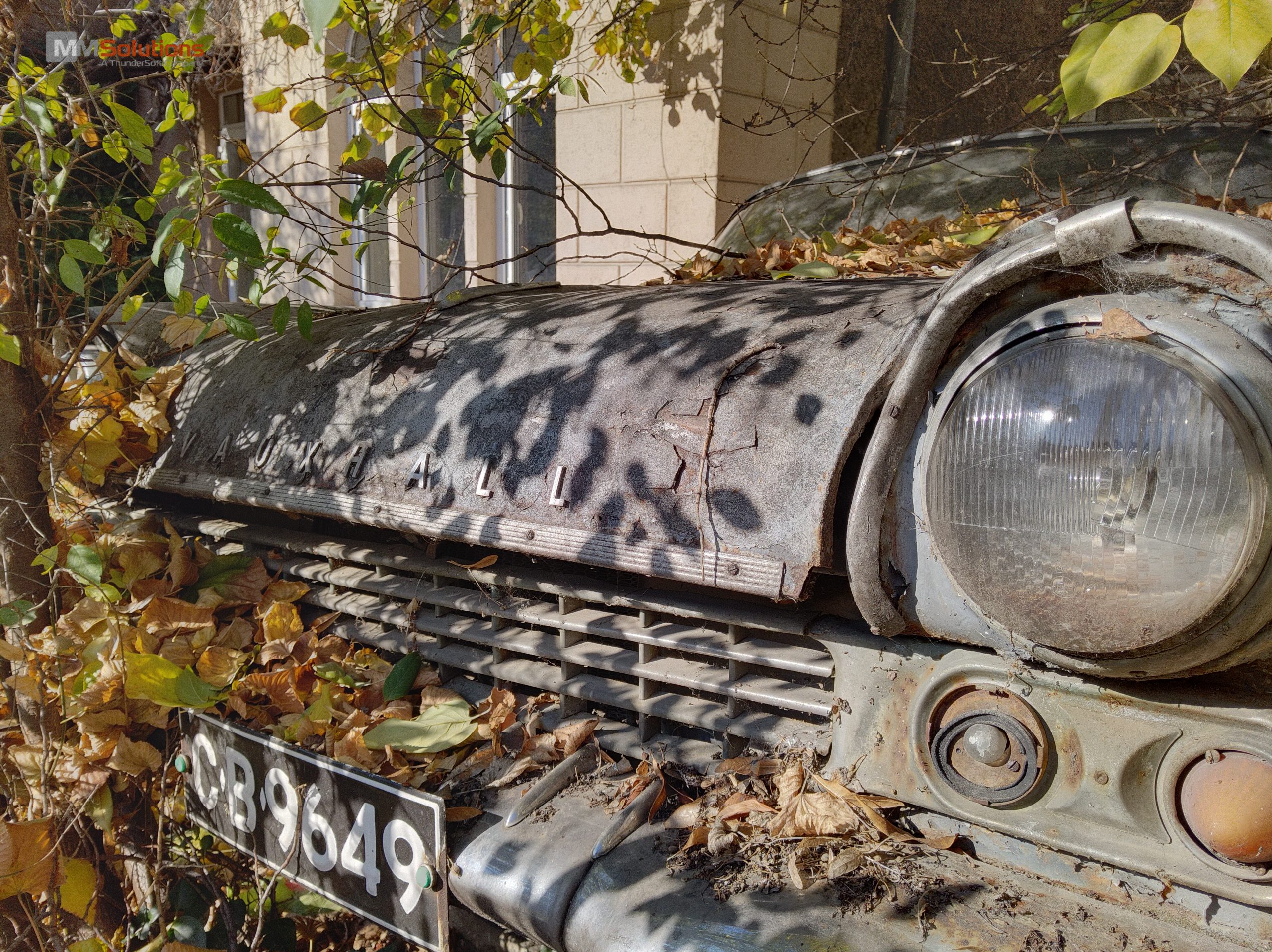
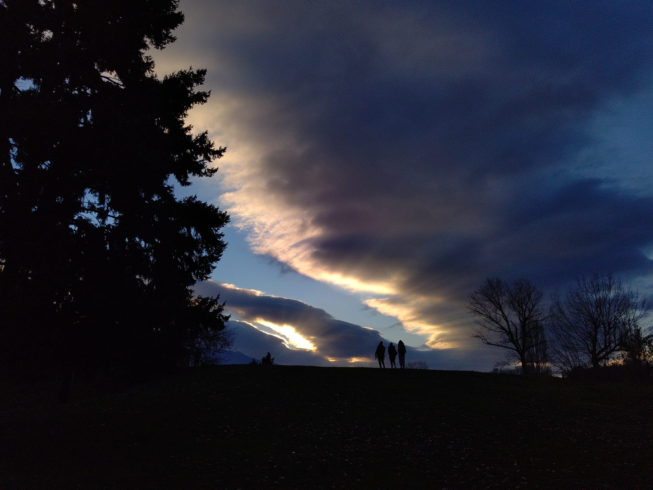


OFF
ON
RAW LOW-LIGHT FILTER (MFNR)
- Noise reduction is essential for quality low-light imaging. Contemporary ISPs incorporate sophisticated noise reduction filters, which behave well at lightness down to about 5Lux. Getting satisfactory image quality in further darker conditions, where the image information is quite weaker than the noise, requires more sophisticated filters.
- The MMS low-light filter runs in the Bayer (RAW) domain, utilizing maximum information that would get contaminated and lost while passing through the ISP processing pipe.
- MMS low-light filter can work as a single- or multi-frame, single- or multi-scale, or combined filter to cover a wide range of customers and capture conditions requirements regarding quality versus processing time.
- Produced RAW output is passed through the ISP, allowing processing with all built-in features.
MMS Low-light filter includes additional features:


OFF
ON
LOW-LIGHT HDR (LLHDR)
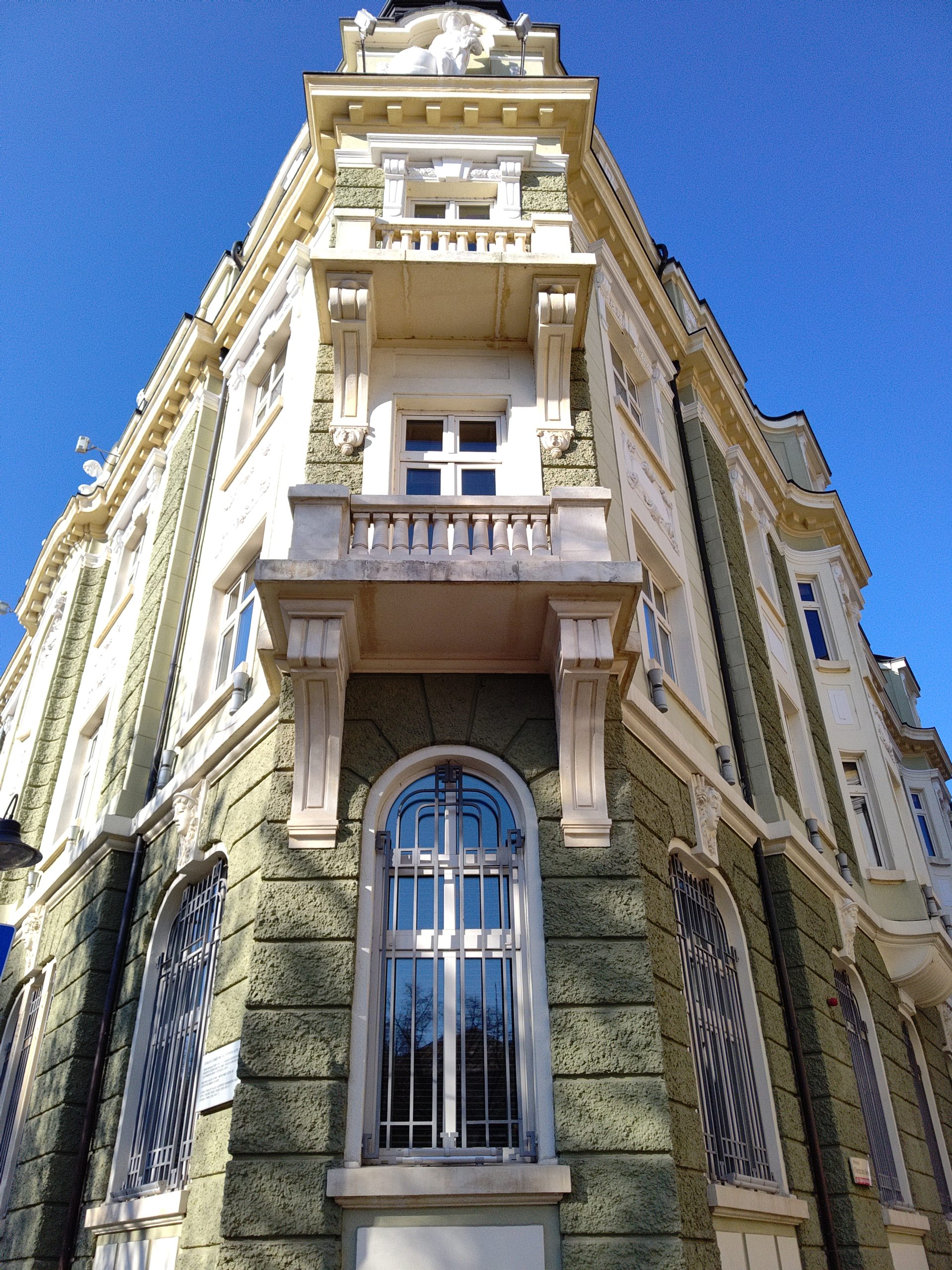
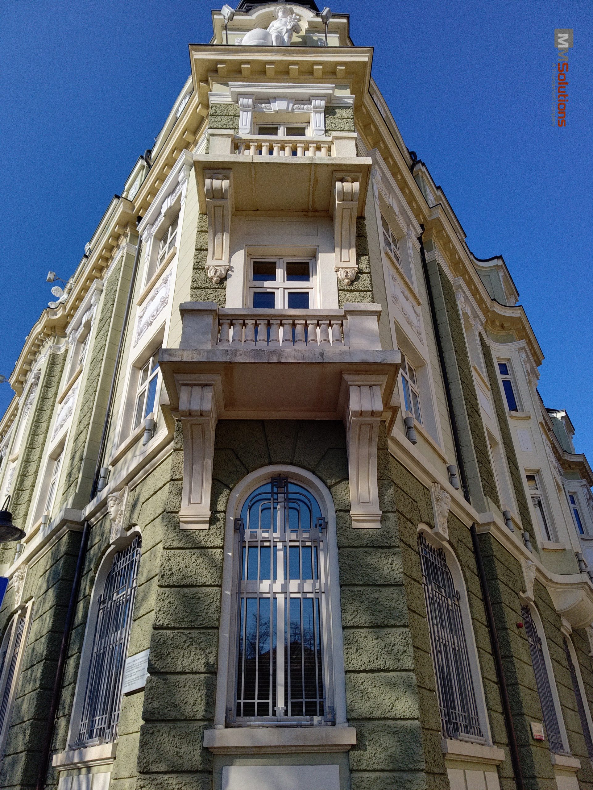
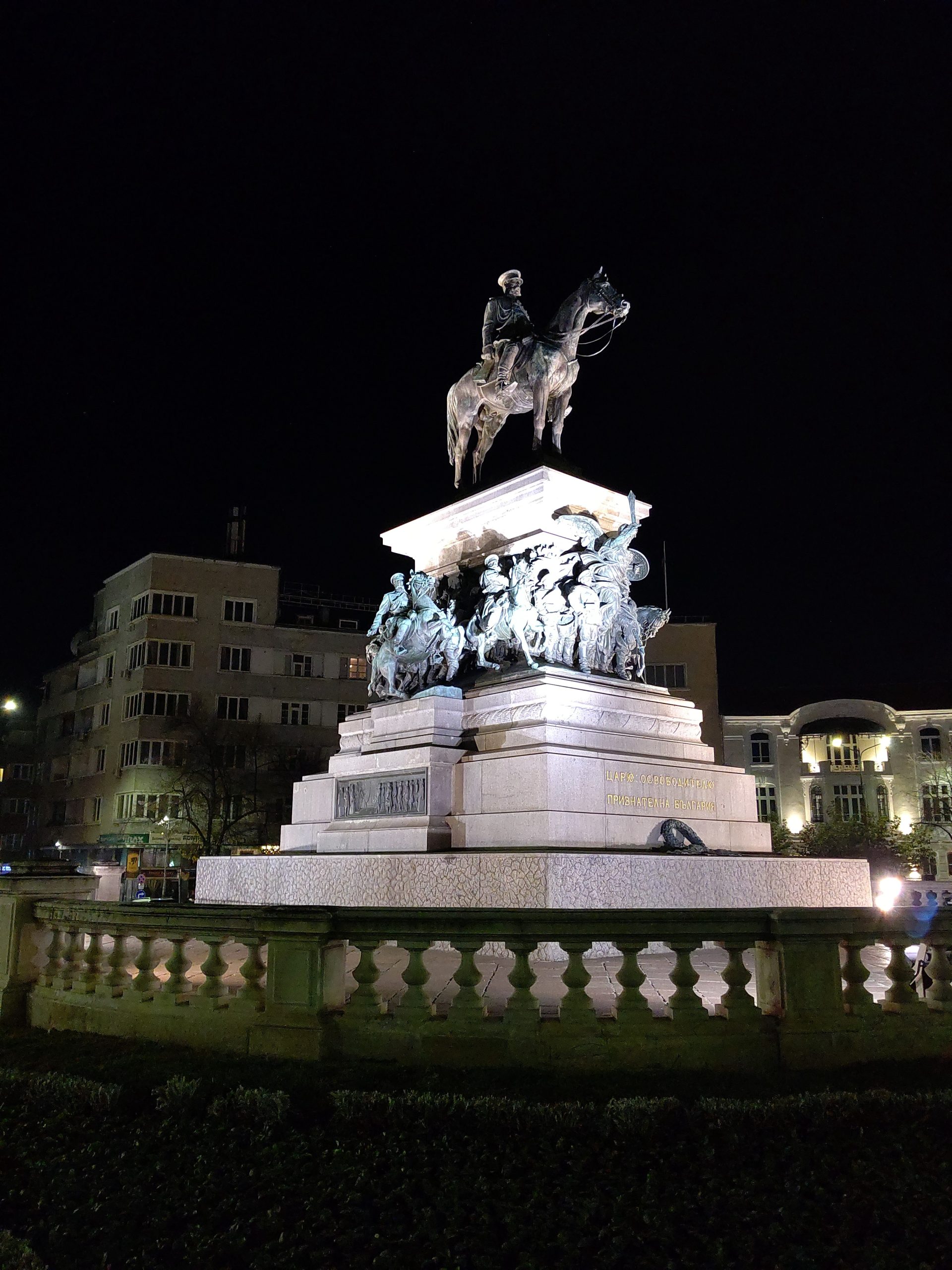
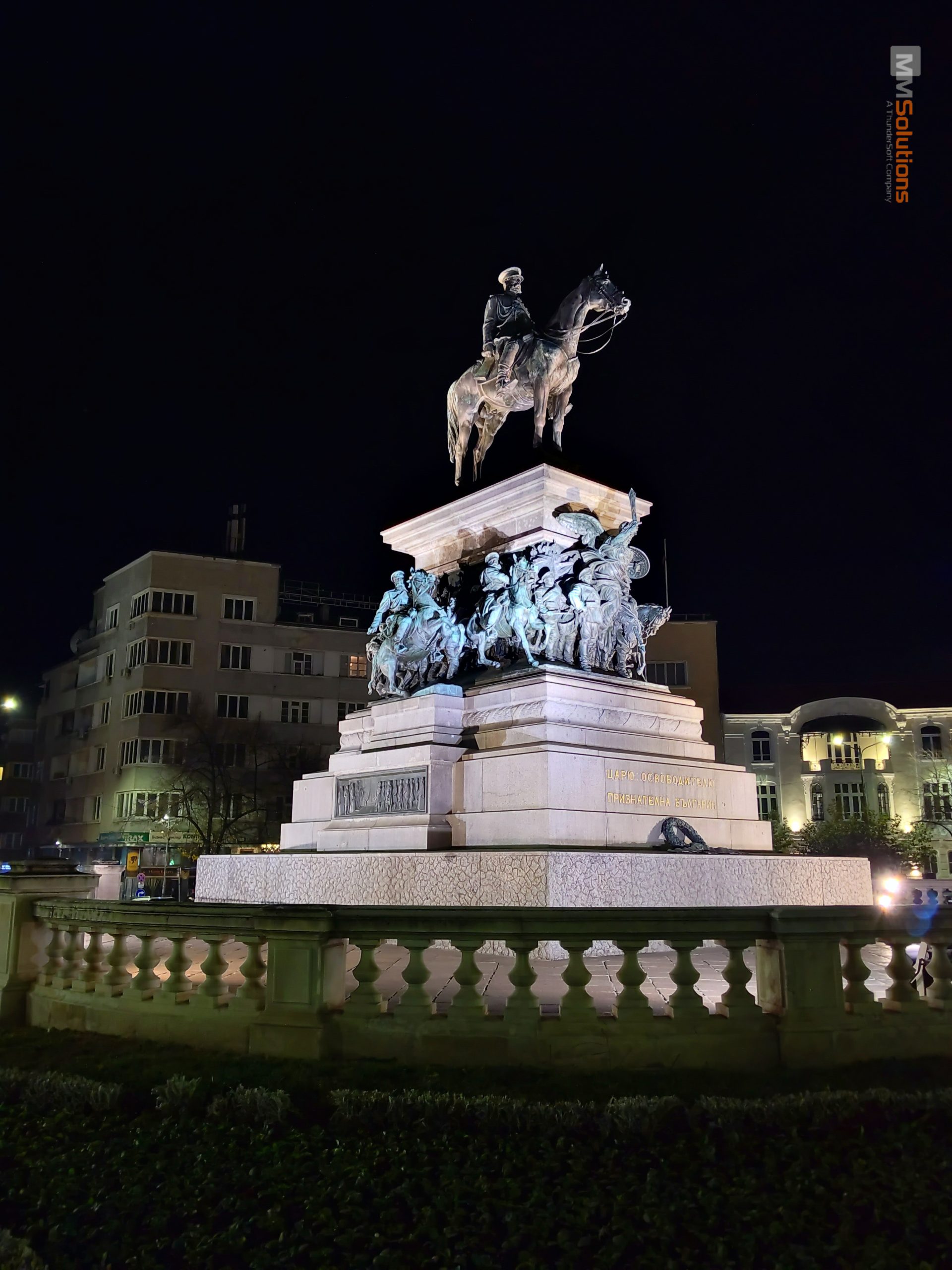
MMS Still-HDR, in combination with the MMS Low-light Filter, produces a high-quality image with low noise levels and details kept in high-light parts of the scene.


OFF
ON
If you are considering introducing our technology or products, or if you are interested in co-creation with us, please feel free to contact us from here.
360° PANORAMA
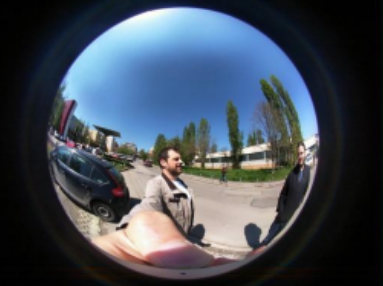
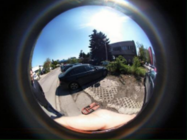
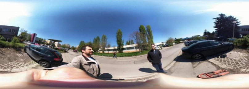
- Noise reduction is essential for quality low-light imaging. Contemporary ISPs incorporate sophisticated noise reduction filters, which behave well at lightness down to about 5Lux. Getting satisfactory image quality in further darker conditions, where the image information is quite weaker than the noise, requires more sophisticated filters.
- MMS low-light filter can work as a single- or multi-frame, single- or multi-scale, or combined filter to cover a wide range of customers and capture conditions requirements regarding quality versus processing time.
360° STITCHING
SMART ZOOM
- Technology allowing for smooth camera-to-camera transition during zoom in and out.
- It supports optical and electronic image stabilization.
- While zooming, MMS Smart Zoom prevents camera transition artifacts like live-view shifts, jumps, and other visual differences.

Smooth transition

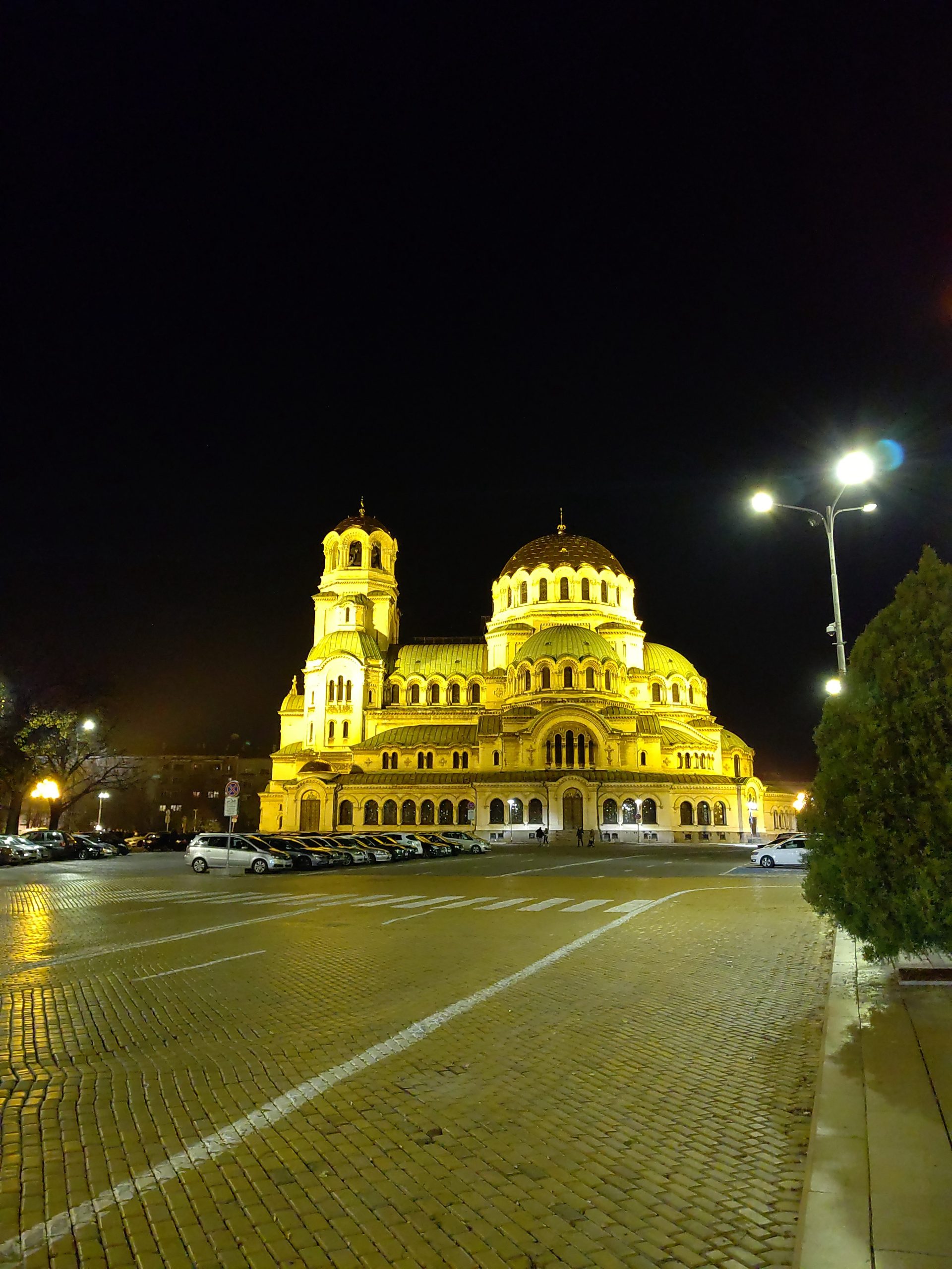
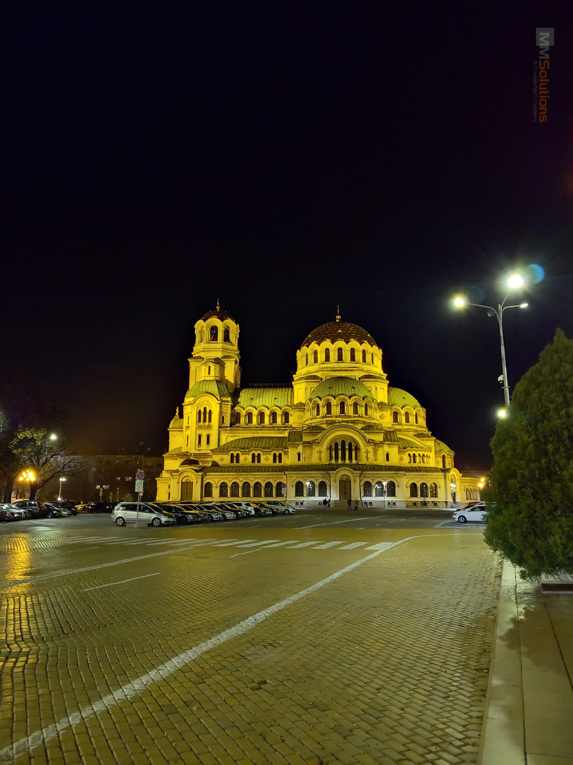
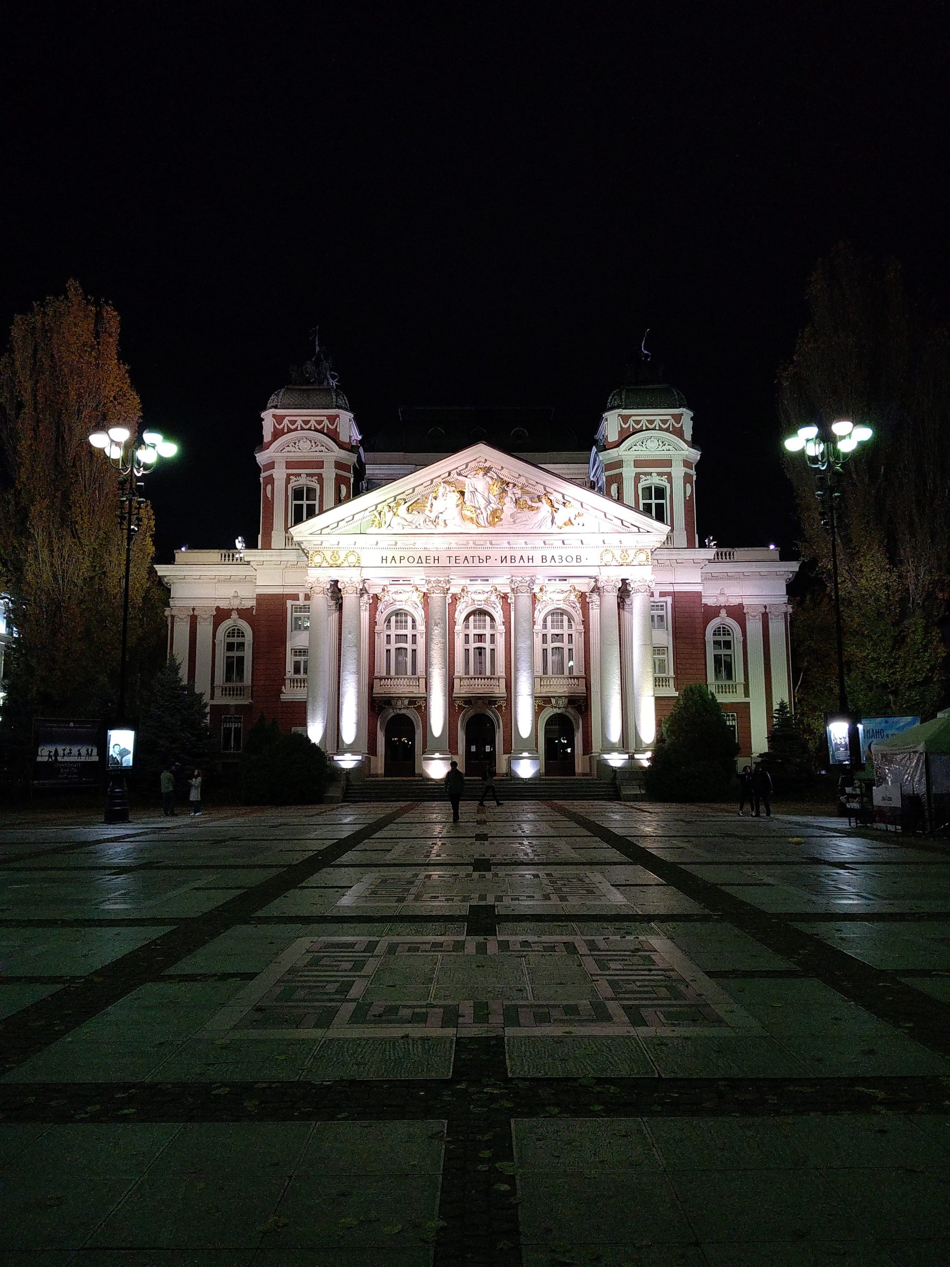
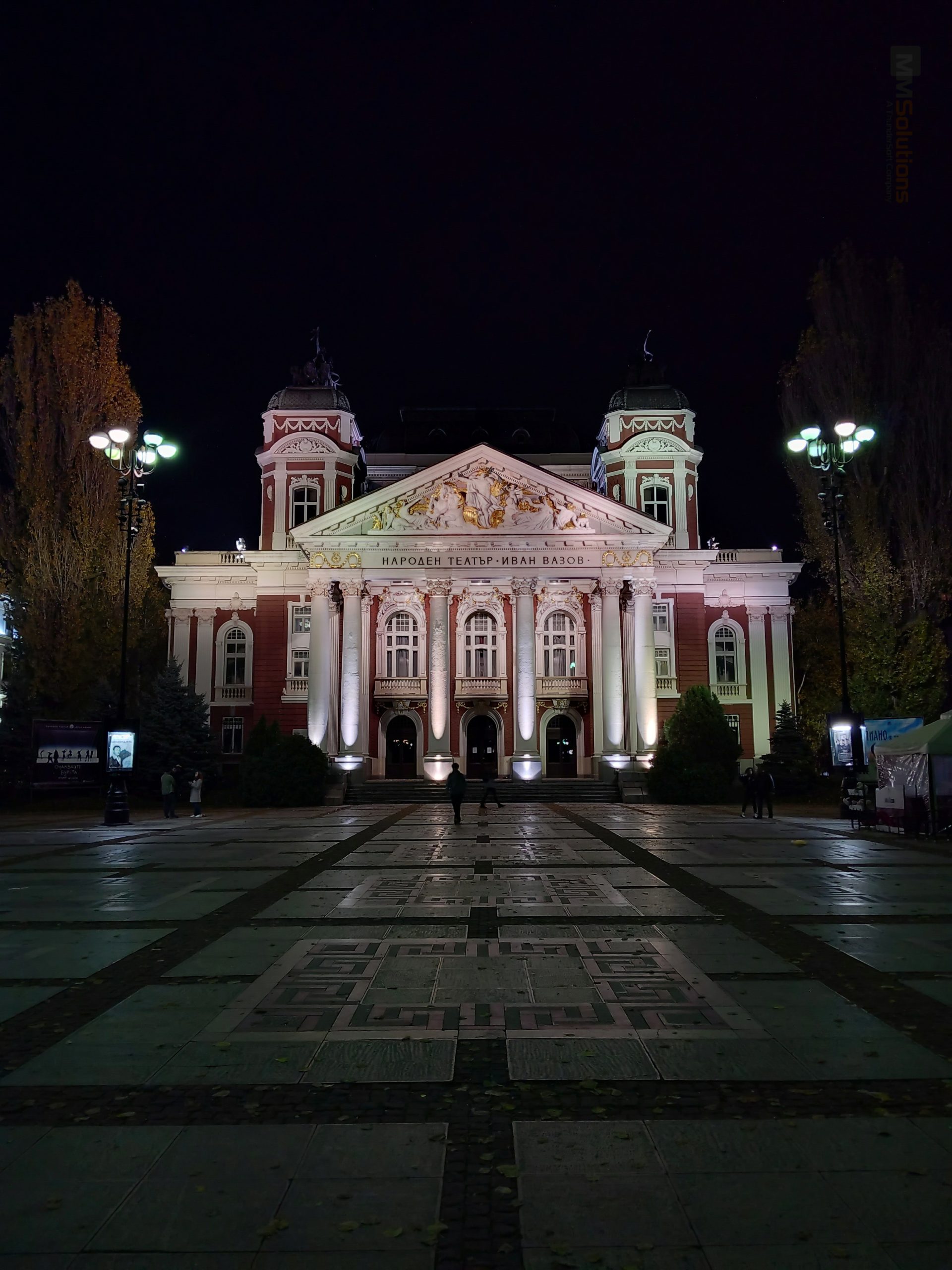
NIGHT
- The night algorithm is used to enhance the image quality in very low light conditions.
- It uses different exposure multi-frame blending to produce bright output with well-preserved highlights and details.
- In this mode, the camera can operate with a longer exposure time to produce less noisy output.


OFF
ON
DISTORTION CORRECTION
- The algorithms can use a GPU for dewarp or any existing specialized HW for that purpose.
- MMS offers a few algorithms for lens distortion correction (dewarp):
- Fully dewarp algorithm for FOV < 140 deg.
- Crop-and-dewarp algorithm to crop a user-defined portion of a fish-eye image and dewarp it.
- Warp algorithm to convert a fish-eye image to an equirectangular (world map) projection.
- Calibration tools for estimating the lens distortions—for the laboratory or factory.
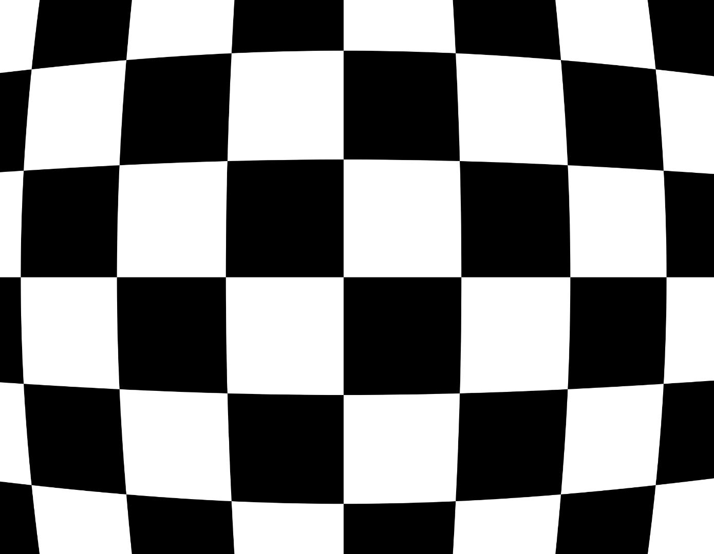
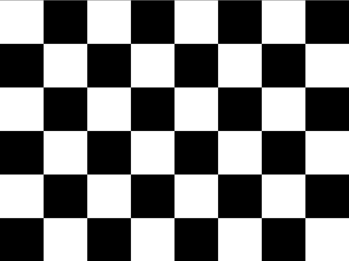
OFF
ON
AUGMENTED REALITY
- The algorithms referred to as “augmented reality” render artificial objects from the frames captured by a real camera while moving.
- Rendering artificial objects is a well-known task that is incorporated into most computer games. In order to render them in the proper places, poses, and orientations, scene analysis is needed.
- Determine the 3D positions of specific scene features and their positions on successive frames.
- Such algorithms are known as SLAM (Simultaneous Localization and Mapping). MMS has implemented and optimized one of the most popular such algorithms (PTAM) on an embedded platform, TI’s OMAP3, achieving 25 fps.
- Determine the camera position and orientation in the scene for every frame.
- Analysis of the features in the scene and finding a ground plane—a plane on which the artificial object should lie.
ELECTRONIC IMAGE STABILIZATION (EIS)
- The MMS EIS algorithm targets stabilizing previews and videos.
- It uses IMU data from the gyroscope sensor and, optionally, camera orientation.
- MMS EIS could use OIS (optical image stabilization) data to combine the motion blur reduction of OIS with the strong stabilization of EIS.
- “Stabilize Horizon”, which guarantees the horizon will be kept horizontal in stabilized video.
- MMS EIS does rolling shutter distortion compensation.
- The Zoom ROI Lock feature helps the user keep the camera view stable while zooming.
CAMERA TYPE AND USE-CASE
CAMERA TYPE AND USE-CASE

Pin-hole input and stabilized cameras.
Used with standard cameras with negligible geometrical distortions, the field of view is typically up to 65°.

Camera stabilization for drones (digital gimbal)
Compensates for drone tilt and vibrations. Optimized for drones with an IMU data rate ≥ 1 kHz. Requires per-module factory calibration of lens distortions.

Wide angle and fish-eye cameras
Used with distorted cameras. The stabilized video may be either undistorted (pin-hole stabilized camera), fish-eye distorted (equiangular stabilized camera), or equirectangular projection. Requires per-module factory calibration of lens distortions. This algorithm is an MMS property.

Dual back-to-back fish-eye cameras for 360° panorama stitching.
This stabilization algorithm is integrated into the MMS 360° stitching algorithm and implements simultaneous stitch and stabilization in a single GPU pass per frame. Uses the per-module factory calibration for stitching. This algorithm is an MMS property.
MMS SURROUND VIEW
SURROUND VIEW MONITOR
FEATURES

Uses GPUs for fast and low-power stitching.

Maintains various views and a few views in the output window.

No camera splitting lines (seamless stitching).

Draws a 3D car model, animations for doors and lights, parking guide lines, sonar distance information, 3D walls, and shows text and icons.

Runtime ground plane estimation and adaptation (GPE).

Maintains transparent car chassis in top view and 3D views.

Adaptive stitching seam.

Adaptive quality for system load.

Adaptive color and brightness correction (ACC).

Inline factory calibration.
MMS SURROUND VIEW MONITORING

Runtime ground plane estimation and adaptation (GPE)
- The car cameras see the ground from very small angles. Hence, even small changes in car position due to tilt, load or tires pressure cause visible shifts of the objects as seen by the cameras, hence ghosts may occur in stitched SVM image.
- GPE finds and tracks points on the ground, constantly estimates the car position with respect to ground and adapts the stitching parameters accordingly.
GPE1 and GPE2 sample videos are taken by an external camera, recording the toy car and the screen, while pushing the toy corners to the ground in order to mimic a changes the car tilt change.

Adaptive seam
- Shoes – only view
A common problem with SVM algorithms is the “shoes-only” issue. When a pedestrian stands exactly on the seam line between two cameras, starting from a car corner, only her or his shoes are visible in the stitched image; the body disappears.
- Curbstones
Due to the large distance between the cameras, they see the surrounding objects from very different view points. Hence, the object looks very different. A typical example are the curbs along the sidewalks. Stitching such different objects inevitably leads to artifacts. To minimize such effects, MMS uses adaptive seams, which can walk around the artifacts.
The video below shows side-by-side comparison of fixed seam (“shoes-only” issue) and MMS’s adaptive seam. The seam moves when an object passes by the car corners.
MMS SVM solution maintains a few seam modes – 1) fixed; 2) seam angle depending on speed, steering and sonar; 3) adaptive seam.

Adaptive color and brightness correction (ACC)
The video below shows a side-by-side comparison of the fixed seam (“shoes-only” issue) and MMS’s adaptive seam. The seam moves when an object passes by the car corners.
MMS SVM solution maintains a few seam modes: 1) fixed; 2) seam angle depending on speed, steering, and sonar; and 3) adaptive seam.
ACC finds and corrects those differences to create a uniform or smoothly changing brightness and color across the scene.

Various views
Various views are maintained, and new ones can easily be added:
- top view(bird-eye)
- top view(bird-eye)
- outside view (3D, arbitrary)
- blind-spot
- etc.
- front/back/left/right
Multiple views on one screen can be defined and rendered by a single SVM API call.
If you are considering introducing our technology or products, or if you are interested in co-creation with us, please feel free to contact us from here.
CAR MODEL RENDERING
- 3D view
- In top-view, the car model is 2D for the fastest rendering. Another view direction is maintained (called “outside” or “3D” view). A 3D model of the car can be rendered as shown in the free-view video example.
- The doors, wheels, and lights can also be animated and rendered according to their status information from the system.
GUIDE LINES
Various guide lines can be rendered. Their curvature follows the vehicle motion and steering information coming through the interface. Distance information from the sonars can be shown too. The shape and colors can be customized. 3D walls can be shown on the 3D views. Arbitrary text and icons can be shown at positions requested via the interface.
The video shows an example of parking guide lines. Different shapes and colors can be implemented and set based on customer preferences.
ADAPTIVE QUALITY-VS-LOAD
The processing in the SVM library is parallelized in a few threads, allowing the most important stages (rendering the output image) to take priority over the less important tasks (adaptations). Hence, when the system is heavily loaded, the SVM automatically decreases its quality, trying to maintain the frame rate. There are configuration parameters that can control the quality-versus-system load trade-off.
ONLINE FACTORY CALIBRATION
- SVM needs to be calibrated on the factory line in order to guarantee good stitching regardless of the camera mounting tolerances. The factory calibration model is embedded in the library. Typically, it runs in automatic mode, requiring the operator to simply approve the result.
- There is also a manual mode, which is entered automatically if the auto-mode fails, providing a convenient interface for the operator to coarsely adjust the camera positions. Then auto-mode finishes the calibration.
Remark: Camera intrinsic parameter calibration is not part of the SVM calibration. For the best quality, the cameras need to be calibrated on their production lines.
If you are considering introducing our technology or products, or if you are interested in co-creation with us, please feel free to contact us from here.